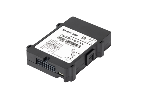
GENERAL SPECIFICATIONS

|
1. |
Device and GPS status LED |
|
2. |
SIM card |
|
3. |
Socket 2x8 pins |
|
4. |
USB interface |

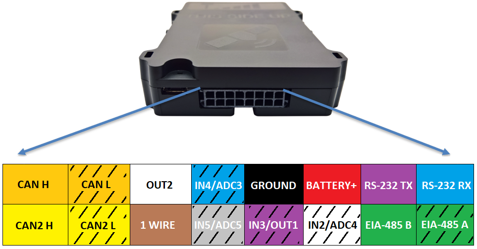
PINOUT OF THE UNIT
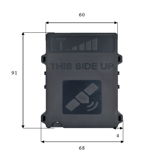
DEVICE INSTALLATION
Central unit is only mounted in inside of the vehicle, it can not be installed in the engine chamber, next to the cabin, or in the area of exposure to direct external conditions. Central unit must be hidden (for example, under the upholstery), as well as protected from moisture exposure. Device must be fastened in a stable position to avoid random twitches and displacements (suspension on cables is strictly prohibited). Central unit must be mounted horizontally. Precise orientation is of particular importance to flawless operation of the system, since the device is equipped with acceleration sensors recording the data which directly affects the results obtained.
POWER SUPPLY | Power supply of central unit has to be connected directly from the vehicle’s battery, using 1A fuse. |
Minus (ground) wire | Ground wire should be connected to the vehicle body. A reliable electrical contact with the body must be ensured, wire has to be bolted. |
Ignition input (combustion lock status) | Connect a wire of the vehicle where voltage is present only when ignition is activated to IN5. |
Universal digital inputs (optional) | Universal Digital inputs (IN2; IN3; IN4; IN5) are intended to collect data from remote devices. |
Analog inputs (optional) | Analog inputs are intended to collect data from remote devices by measuring voltage. ADC3, ADC4 range 0-40V. |
DEVICE DIAGNOSTIC
| Long blinks count | Description | Actions to be taken |
|---|---|---|
1 long blink | Ready to go! | |
2 long blinks | Try to reboot device or force to connect to server. | |
3 long blinks |
| |
4 long blinks | Check the SIM card. Most probably network provider did not enable GPRS service. | |
5 long blinks | Check the SIM card.
| |
6 long blinks | Check the SIM card.
| |
7 long blinks |
|